Synchronous reluctance motor torque ripple - QuickField simulation example
Synchronous reluctance motor features a stator of a synchronous motor with three phase winding. Due to stator slotting the torque ripples.
How to find torque ripple in synchronous reluctance motor?
Answer Typical applications Geometry
Given
Task
Solution
First we take the rotor out of the model, set momentary values of the currents at ωt=0 and solve the problem. This way we get the stator magnetic field direction. Then we put the rotor back in the model, align the rotor pole with the stator field and rotate the rotor once by the load angle φ. That is the initial position.
Results
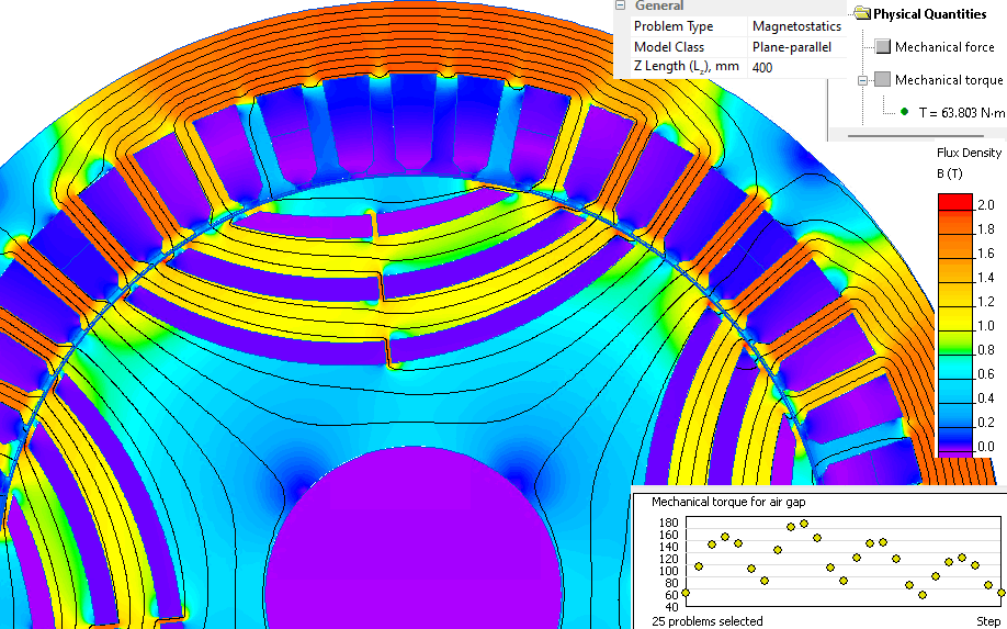
Field picture of the magnetic flux density distribution in a synchronous reluctance motor:
Reference: Wikipedia Torque ripple
Engineering question
Set up a plane-parallel QuickField DC Magnetics problem for a synchronous reluctance motor and evaluate torque ripple from computed field results.
synchronous reluctance motors, reluctance rotor machines, torque ripple reduction studies
Download
Simulation problem
Problem Type
Plane-parallel problem of DC magnetics.
Axial length of the motor is 400 mm
Stator slots number Z1 = 48, number of phases m=3, number of poles 2p=4.
Stator winding current density j = 3 A/mm²
Load angle φ = 6°
The B-H curve for the stator and the rotor:
Calculate an average torque.
We presume that the rotor rotates synchronously with the stator magnetic field. So we can simulate a series of static problems with predefined rotor positions to measure the torque.
At some moment of time the rotor pole is aligned with the stator tooth and at another moment of time it is aligned with the stator slot. That causes the torque ripple*.
When we rotate the rotor we should also adjust the electric currents' momentary values. The currents in the stator winding are sinusoidal functions of time: j = j0 * cos(ωt + phase shift), where phase shift for phase A is 0°, for phase B it is -120° and for phase C it is -240°. The rotation of rotor by 1° corresponds to ωt increment by p*1°.
Then we are going to increment ωt and set new momentary values of the currents. Magnetic field would rotate by some angle and we also rotate the rotor by the same angle. This way we can get the second and futher positions at which the torque is measured. In general case we should make a full turn. But due to the fact that Z1/2p/m is an integer we repeat this only till ωt = 60°.
To automate the creation and solution of a series of problems, it is convenient to use the LabelMover utility, which will automatically change the model and measure the electromagnetic torque.
Average torque value is 113 N*m. Torque ripple* chart:
Related examples