QuickField Student Edition

User manual

Data Libraries

Free tools

Main >> Downloads

Induction motor design

This example automates calculation of induction machine parameters. The worklow and equatons are taken from [1, Chapter 15. IM DESIGN BELOW 100KW AND CONSTANT V AND f].

Specify motor parameters

Rated power, PnkW
Line voltage, V1V
Frequency, fHz50 60
Poles, 2p-
Power factor, cos(φ)
Efficiency, η
Stack aspect ratio, λ = Stator Length / Stator Diameter
1.5
Short Long

Press the Design a motor button to calculate motor dimensions.

There are some technological limitations and rules of thumb that we try to follow.

Maximal wire diameter for the stator windingmm
If the stator winding conductor diameter is greater than the maximal allowed, we can try to place two or more wires in parallel.
You can specify maximal number of parallel wires.
From technological limitations, the tooth width should not be under 3.5 mm.
You can specify other value here.
mm
Target stator current density (4.. 8 for copper)A/mm²
Target rotor bar current density (2.5.. 3.5 for aluminum)A/mm²
Target stator tooth flux densityT
Target rotor tooth flux densityT
Target stator back core flux density
Usualy 1.4... 1.7
T
Lamination factor, KFe

Calculated parametes

1
Stack length, Lmm
Stator bore diameter, Dismm
Stator outer diameter, Doutmm
Air gap length, gmm
2
Slots per pole and phase, q
Slots number, Ns = m * 2p * q,
where m=3 phases
Coil pitch, y
Coil pitch correction, Δy

Phase color notaion: A - X, B - Y,C - Z.

3 Stator slot type:

Slot dimensions, mm

d1 d2
h1 h2
s1 s2
Tooth width, bsu
4 Rotor slot type:
Entire slot area is filled with conductor.

Slots number, Z2 =

Slot dimensions, mm

d1 d2
h1 h2
s1 s2
Tooth width, bsr
5 Rotor bar conductivity at expected temperature, MS*m

In 2D AC magnetic analysis only the rotor bars are included. In the model the rotor bars are specified as short-connected.
In reality the rotor bars are connected with the end rings.
To take into account the resistance of the end rings you might like to reduce the conductivity of the rotor bars.
Attenuated conductivity of the rotor bars, MS/m

6 For the steel parts you specify steel magnetization curve data and zero electrical conductivity as the core is laminated.
To take into account steel losses you specify loss coeffitient, P = Kh * B² * f, W/m³.
StatorRotor
Magnetization curve:

Kh =

B(T) H(A/m)

Magnetization curve:

Kh =

B(T) H(A/m)

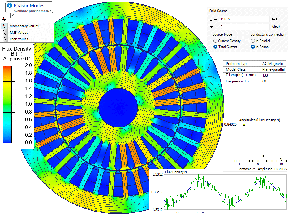
FEM simulation with QuickField

induction generator file.

References:
1. Ion Boldea, Syed A. Nasar. The Induction Machines Design Handbook, Second Edition. Electric Power Engineering Series. Taylor & Francis, 2009.