Induction motor magnetization curve - QuickField simulation example
Engineering question
How to calculate the magnetization curve and magnetizing current of an induction motor?
Answer
To find the magnetization curve and magnetizing current, run a series of AC Magnetics simulations across a range of stator current levels. For each level, extract the first harmonic of the airgap flux density to plot the curve. The magnetizing current is the value on this curve that corresponds to the motor's rated airgap flux density.
Typical applications
induction motor design, no-load test verification, magnetizing current estimation
Download
- Download simulation files (files may be viewed using any QuickField Edition).
Simulation problem
This simulation model was generated automatically using the QuickField Induction Motor Model Generator.
Problem TypePlane-parallel problem of AC magnetics.
Geometry
Stack length L = 133 mm.
Stator outer diameter Dout = Ø190 mm.
Stator bore diameter Dis = Ø113 mm.
Given
Rated current I = 9.34 A (RMS), frequency f = 60 Hz.
Airgap flux density Bgap = 0.69 T (amplitude).
Turns per coil side N = 15.
Magnetic permeability of the steel core (35PN250):
Task
Calculate the airgap flux density as a function of stator current, and find the magnetizing current at the motor's rated airgap flux density.
Solution
The simulation is performed at synchronous speed (zero speed with zero slip), so the rotor carries no current. In the model, this is achieved by setting a zero conductivity for the rotor.
Each side of a winding coil (all N turns of that layer) is modeled as a single block, so the block's current is the total ampere-turns:
AmpereTurns = N·I = 15·9.34 = 140.1 A.
In QuickField we set the magnitude:
Total current = AmpereTurns·√2 = 140.1·√2 = 198.2 A.
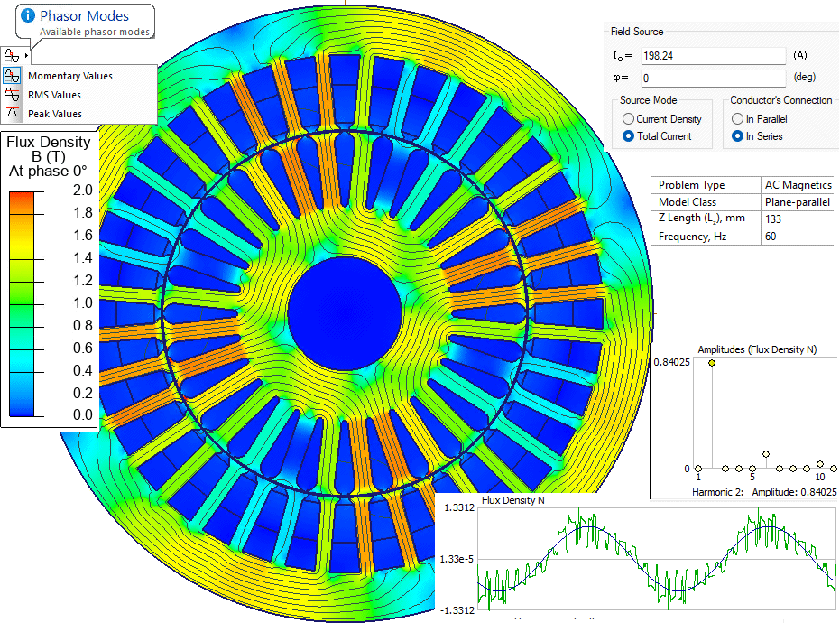
When analyzing results, switch to momentary values. The amplitude of the first (fundamental) harmonic of the airgap field is found with the Harmonic Browser add-in, run on the air gap contour.
Results
Airgap flux density vs. stator current (magnetization curve):
| Total current (magnitude), A | Phase current (RMS), A | Flux density (magnitude), T |
|---|---|---|
| 63.55 | 3.00 | 0.61 |
| 74.765 | 3.53 | 0.66 |
| 87.958 | 4.15 | 0.70 |
| 103.48 | 4.88 | 0.73 |
| 121.74 | 5.74 | 0.76 |
| 143.23 | 6.75 | 0.79 |
| 168.5 | 7.94 | 0.82 |
| 198.24 | 9.35 | 0.84 |
The magnetizing current at the motor's rated airgap flux density (0.69 T) is about 3.94 A (RMS) - 42% of the rated current.
Magnetic field distribution at rated current:
References:
Ion Boldea, Syed A. Nasar. The Induction Machines Design Handbook, Second Edition. Electric Power Engineering Series. Taylor & Francis, 2009. (Section 15.8, The Magnetization Current - the equivalent hand-calculation this example cross-checks with FEM.)