Brushless permanent magnet DC motor
QuickField simulation example
BLDC motor has a 51-slots stator with a 3-phase winding and a 46-poles external rotor with permanent magnets. Rotor pole and stator slot numbers do not match to reduce the cogging torque.
Stator winding is distributed to reduce the radial forces acting on the rotor. There are 51/3=17 slots per phase so the winding is distributed unevenly in groups of 3 and 4 slots.
We do not consider the design process here. Instead, our task is to calculate the back EMF.
Problem type:
Plane-parallel problem of DC magnetics.
Geometry
Motor Z-length is 27.2 mm*.
Given
Rotor speed n = 440 r.p.m (46 s-1), poles 2p = 46.
Stator slots number z1 = 51, number of turns w = 4, phases m = 3.
Permanent magnet relative magnetic permeability μ = 1.1, remnant flux density Br = 0.33 T.
Task
Calculate the back EMF in a three phase winding in no-load mode.
Solution
Coercive force of permanent magnets Hc = Br / μ / μ0 = 238 kА/m.
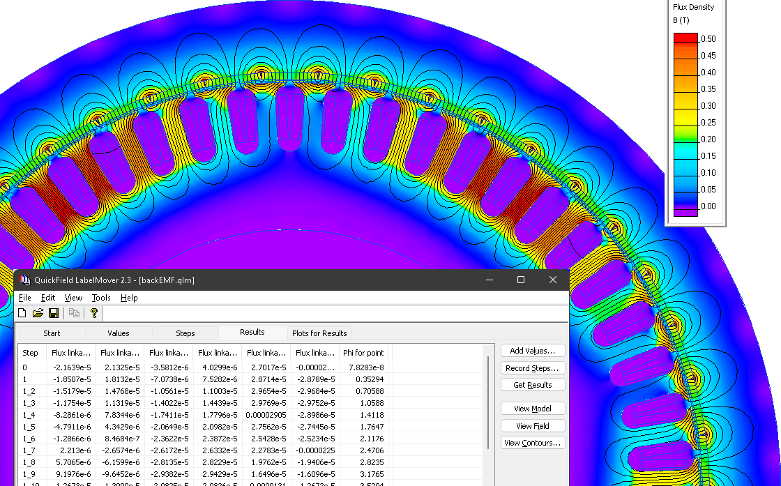
A series of static problems is simulated with different rotor angular positions. At each position the flux linkage with stator windings is measured. LabelMover parametric tool is used to automatically change the model and measure the average flux linkage in each half-coil.
Then the full flux linkage of the coil is calculated as Flux = (ΦA - Φa) * (z1 / m) * w
The electromotive force is calculated as EMF = - n * (ΔFlux / Δangle)
Result
Magnetic field distribution in the motor.

Referece
*Motor dimensions are taken from the paper by Conggan Ma, Qiongyao Li, Ping Zheng, Shengsen Zhou, Haibo Gao, Jianguang Fang, Yanyan Wang Effects of static eccentricity on the no-load back electromotive force of external rotor permanent magnet brushless DC motor used as in-wheel motor
- Download simulation files (files may be viewed using any QuickField Edition).