High frequency line trap - QuickField simulation example
Electromagnetic forces and resulting mechanical stresses in a high-frequency line-trap body subjected to the specified short-circuit current loading.
How to find mechanical forces and stresses in high-frequency line traps?
Answer Typical applications Geometry
Given
Fiberglass case Young's modulus E = 20 GPa, Poisson's ratio ν = 0.11.
Task
Solution
Results
Mechanical stress in the aluminum cable, wave trap deformed shape (zoomed 1000:1) and Ampere force value acting on the ending turn:
*Reference: Line trap in Wikipedia.
Engineering question
Calculate electromagnetic forces in the axisymmetric AC-magnetic model, transfer them to the coupled stress problem, and evaluate mechanical stresses in the line-trap coil and body.
air-core line traps, transmission line filters, wave trap coils
Download
Simulation problem
Problem Type
Axisymmetric multiphysics problem of AC magnetics coupled to Stress analysis.
Current (peak value) I = 12 kA, frequency f = 50 Hz.
Aluminum cable cross-section area A = 2 cm², conductivity σ= 37 MS/m;
Young's modulus E = 70 GPa, Poisson's ratio ν = 0.34.
Determine forces and mechanical stresses in the high-frequency line trap body.
The actual spring-coil is modelled as a set of circular turns embedded in a fiberglass case. That facilitates 2D axisymmetric simulation.
The solution consists of two stages: the calculation of forces in a AC Magnetic problem, and then the calculation of mechanical stresses in a mechanical problem. The transfer of forces from AC Magnetic problem to mechanical one is automated using the coupling mechanism.
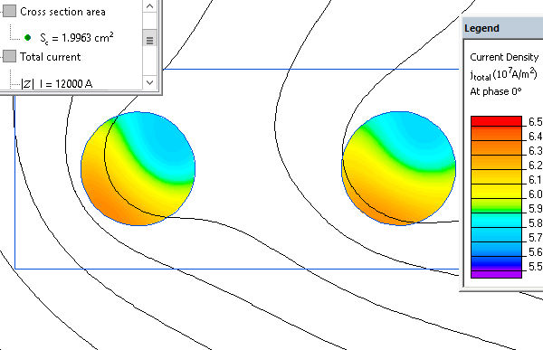
Current density distribution in the aluminum cable:

Video
Related examples