PCB ground plane heating - QuickField simulation example
The voltage is applied to the sides of conducting sheet placed vertically and surrounded by the still air. The flowing current heats the sheet due to resistive losses. The front and back surfaces of the sheet are cooled by the air (natural convection).
How to find PCB sheet resistive heating?
Answer Typical applications Geometry
Given
Task
Solution
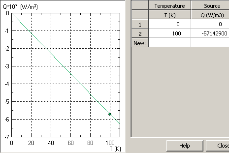
The convection from other surfaces is ignored. The convection is modelled by the volume heat sink Q(T) = -k·T, where coefficient k = 2α/d.
Results
Temperature distribution in the pcb (overheating)Engineering question
Set up a plane-parallel QuickField Steady-state Heat Transfer problem for a PCB ground plane and evaluate resistive heating from computed field results.
printed circuit boards, copper planes, electronics cooling boards
Download
Simulation problem
Problem Type
Plane-parallel multiphysics problem of DC Conduction coupled to Heat Transfer.
Sheet thickness d = 0.035 mm;
Material resistance ρ = 2·10-8 Ohm/m;
Current I = 10 A;
Material heat conductivity λ = 380 W/K-m;
Convection coefficient α = 10 W/K-m²;
Calculate the temperature and potential distribution in a conducting sheet.
The resistive losses are calculated in the DC conduction problem. Then these losses are transferred to the linked heat transfer problem.
The pcb_current.pbm is the problem of calculating the current distribution, and pcb_heat.pbm analyzes temperature field.
The sheet is cooled by convection from the front and back surface (total) f(T) = -α·(T - T0)·(Afront + Aback), where α is a convection coefficient, and T0 is an ambient temperature, Afront, Aback - area of front and back surfaces, respectively.
Potential distribution and current paths in the pcb

Video
Related examples