Electrical generator winding loss - QuickField simulation example
There are permanent magnets glued to the rotor. There is a 3-phase concentrated winding on the stator poles. The task is to calculate eddy current losses in the conductors. The problem is divided in the parts:
How to find eddy current loss in generator winding?
Answer Typical applications Geometry
Given
Task
Solution
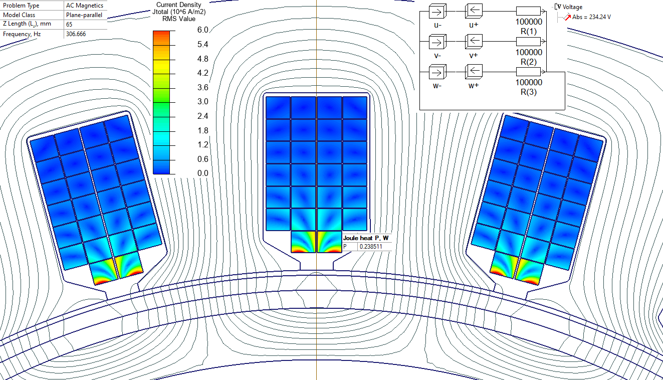
In AC problem we specify the frequency of the generated voltage: f = 2300/60 * (permanent magnets number /2 ) = 306.66 Hz.
Results
EMF unity harmonic is 41 V per pole. There are 8 pole windings connected in series, so the total voltage is 328 V (magnitude). Next, we replace permanent magnets with the current layer and want to get the same magnitude of the unity harmonic.
In the AC magnetic problem the EMF is 323 V, which is close to the value calculated in the DC magnetic problem (328 V).
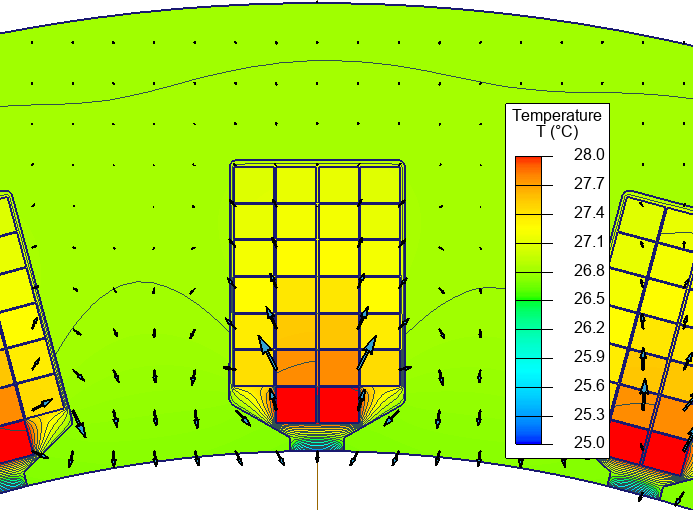
In the thermal problem the temperature distribution was calculated. Only the winding losses caused by the magnetic field fluctuation were specified. No other losses are taken into account - this way we can clearly see the thermal effects caused by the specific losses. Losses are automatically transferred from AC magnetic to Heat transfer problem using QuickField problems coupling.
1. First we simulate a set of DC magnetic problems with various rotor positions. The stator winding is disconnected and carries no current. The result of the analysis is the flux linkage with conductors vs rotor position dependency, which is transformed to EMF vs time dependency.
2. Then we replace the permanent magnet with the current layer and run an AC magnetic problem. The actual magnetic flux density distribution calculated in the DC magnetic problem is replaced with a sinusoidal flux density distribution. So, we take into account only the unity harmonic. The current layer produces the running wave of the magnetic field in the air gap. The layer parameters are adjusted so that the EMF induced matches the unity harmonic that was calculated in the DC magnetic problem.
3. Calculate temperature distribution.
Engineering question
Set up a plane-parallel QuickField AC Magnetics problem for a generator winding and evaluate eddy current loss from computed field results.
permanent magnet generators, stator windings, generator phase conductors
Download
Simulation problem
Problem Type
Plane-parallel problem of DC magnetics, AC magnetics and Heat transfer.
Motor z-length is 65 mm.
Rotational speed is 2300 rpm.
Number of turns per pole is 15.
Coercive force of the permanent magnet is 750 kA/m, residual flux density is 1.04 T.
Magnetic permeability of steel is 1000.
Calculate the eddy current losses in the winding.
A set of DC magnetic problems with different rotor positions is automatically generated and solved using LabelMover. It is more convenient to keep the rotor motionless and rotate the stator. This way there is no need to correct magnetization direction of permanent magnets on each step.
The flux linkage vs. rotor position dependency is converted to EMF vs. time dependency:
Equation Ht * cos (ωt + phase) defines the running wave, where Ht=200'000 A/m is the magnitude of the distributed current and phase depends on the coordinates. I
In QuickField AC magnetic problems all terms are functions of ωt, so in input parameters we need to specify only the Ht and the phase = 8*phi, where phi is a built-in angular coordinate.
In real case the stator is motionless and the rotor rotates. The animated set of pictures is made in inverse manner - the stator rotates and the rotor is motionless.
Eddy current losses in the conductor near the air gap is 0.2385 W per 65 mm on the slot length.
Conductor temperature rise is 28 - 20 = +8 °C
Related examples