Split busbars unbalance current
Example is prepared by Ivan De Luca (I.E.C.I. Engineering srl.)
Busbar system is used to supply the electric current from the transformer to the glass melting electric furnace. Extensive study is required to design the most effective busbar system and minimize power losses.
Problem Type
Plane problem of AC magnetics.
Geometry
Busbars length is 30 meters.
CBAABC configuration:
ABCABC configuration:
Given
Electrical conductivity of aluminum is 33.5 MS/m
AC current is 1 kA (r.m.s.) per pair of busbars.
Frequency is 50 Hz.
Task
Calculate current distribution in the busbars and power losses. Compare ABCABC and CBAABC configurations.
Solution
Parallel conductors are being assigned a single label and parallel connection is specified in the label properties.
We utilize the electric circuit to specify labels connection.
Results
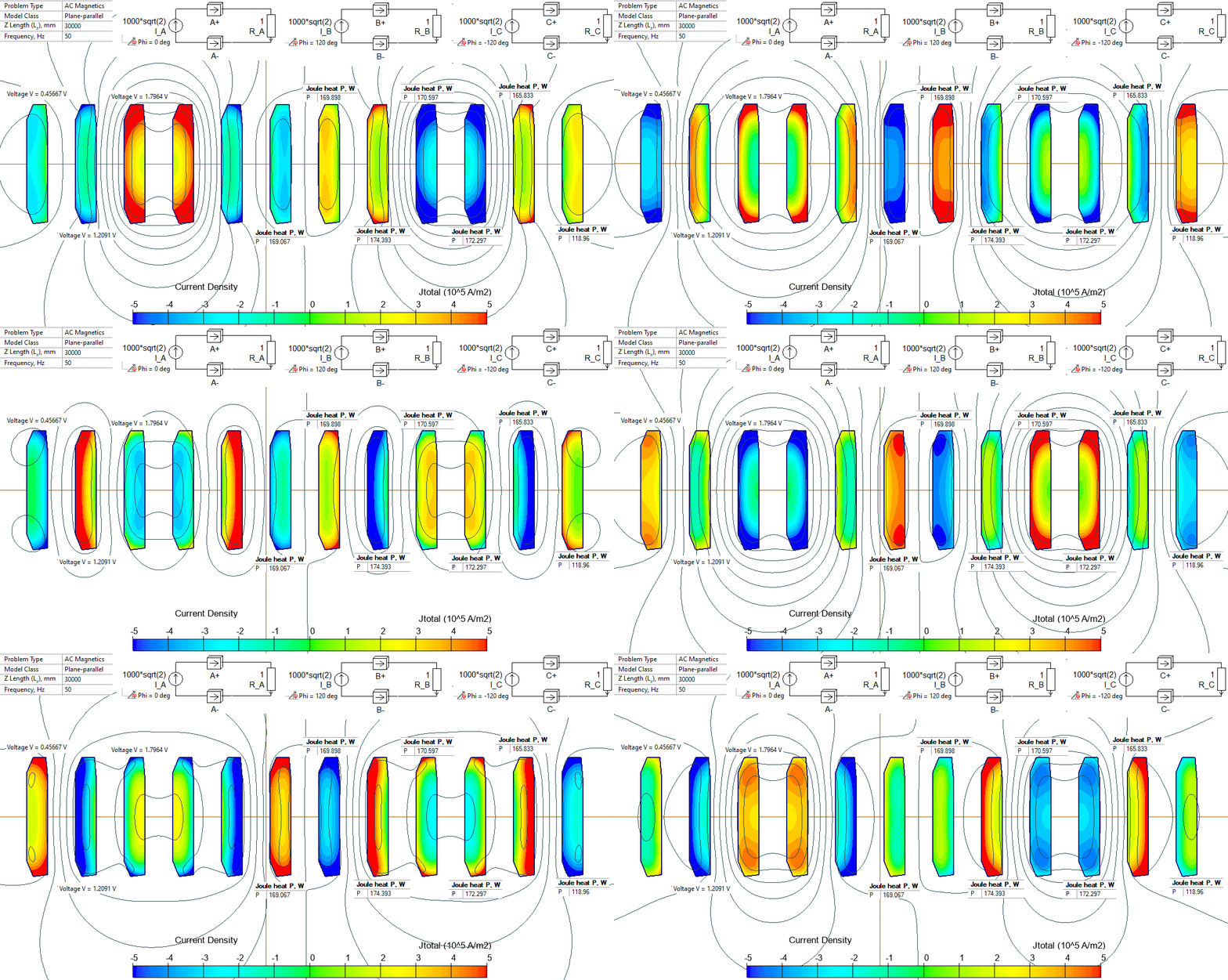
Current is distributed more uniformly in the CBAABC than in the ABCABC configuration.
Current and power loss distribution in the CBAABC configuration.

- Download simulation files (files may be viewed using any QuickField Edition).