Wireless charging - QuickField simulation example
Example courtesy of Sergey Chishko
Wireless chargers, which are widely advertised today, are conventional air transformers that may (or may not) contain magnetic paths. Normally, the transmitting part (primary coil) is fixed while the receiving part (secondary coil) is located in a mobile device and can take different positions relative to a primary coil. Coils can be of a different shape, but most commonly they are either square or circular (as the one in the picture). In this example the influence of capacitances in series with primary and secondary coils on the energy transfer is studied.
How to find coil coupling in wireless charging coils?
Answer Typical applications Geometry
Given
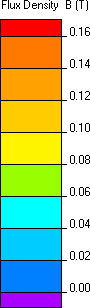
Task Solution Results Magnetic flux density in the cross-section of the wireless charger:
Engineering question
Set up an axisymmetric QuickField AC Magnetics problem for wireless charging coils and evaluate coil coupling from computed field results.
wireless charging coils, inductive power transfer coils, air-core coupling coils
Download
Simulation problem
Problem Type
Axisymmetric problem of AC magnetics.
Core has a linear relative permeability of μr = 1000;
Current in coils has an electrical frequency f = 10 kHz;
Primary coil is fed from a current source I1 = 4 A;
Load is modeled with resistance Rload = 1 Ω.
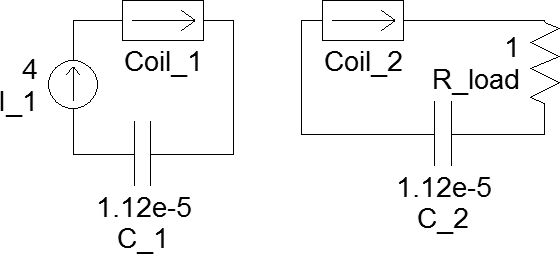
To obtain the values of coils self-inductances and to solve the model coupled with external circuit to study the effect of adding capacitances.
The most effective energy transfer happens when primary and secondary parts work in resonance. In order to operate circuits in resonance at defined frequency a certain capacitance value shall be added to both circuits. This value directly depends on the self-inductance of the circuit as C = 1/(ω²·L).
Inductance non-linearly depends on the core magnetic properties, eddy effects in the coils and core, mutual orientation of the coils. In order to simplify the model and omit non-linear effects, the core permeability is assumed to be constant. Also, dimensions of conductors are small and core is non-conductive, therefore, the eddy current effects are negligible.
With stated assumptions self-inductances of the coils are L1 = L2 = 22.65 μH. Thus, capacitances are C1 = C2 = 11.20 μF.
Without capacitances: primary part takes S1 = 6.88 VA and power in load resistance is Pload = 4.46 W.
With capacitances: primary part takes S1 = 13.68 VA and power in load resistance is Pload = 12.68 W.
Video
Related examples